Author: Brian Stevens
Editor: Chris Hinkey
Special Thanks: Ryan Mennecke for assisting in installation and optimization
Goals and Tasks
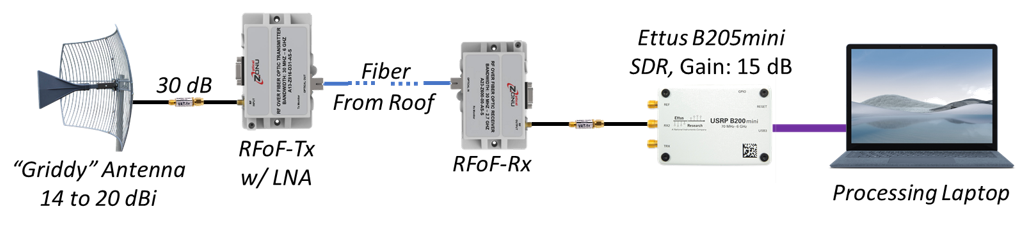
Geon has leveraged parabolic antennas and Radio Frequency over Fiber (RFoF) to maximize signal quality of local 4G Long Term Evolution (LTE) frequency carriers within Geon’s lab, which has no line-of-sight (LOS) to the signal sources. A least squares SINR estimation is used to measure and optimize signal quality. A functional block diagram of our signal setup is shown below and will be discussed in detail throughout the rest of this post.
Equipment and Parts
1. Griddy by Waveform:
– https://cdn.shopify.com/s/files/1/0358/5537/files/ANT66NF-GP_Spec_Sheet_v3.pdf?v=1690929331
2. RFoF Transmitter by OpticalZonu:
– Part#: 3950-A23-Z816-00-AS-S-ND
– https://www.digikey.com/en/htmldatasheets/production/10386433/0/0/1/oz816
3. RFoF Receiver by OpticalZonu:
– Part#: 3950-A13-Z816-D31-AS-SL-ND
– https://www.digikey.com/en/htmldatasheets/production/10386433/0/0/1/oz816
4G/5G Background
Why: LTE, commonly associated with the term “4G”, is a terrestrial signal that provides wireless access to mobile devices. These signals allow us to listen to Spotify on the way to work, follow instructions via Google Maps, and be interconnected while we move away from our household Wi-Fi signals. In this blog post, we talk about LTE as it is still heavily used within the new “5G” standard and very closely related in waveform physical properties to 5G, unlike previous iterations of the cellular standard. In a future post, we will investigate local 5G New Radio (NR) signals. Either way, 4G and 5G cellular signals surround us daily and provide connectivity to the very important electronic in everyone’s pocket, the cell phone.
What: 4G LTE is called a cellular technology because towers provide access within geographically isolated areas (cells) to improve geographical reuse of the radio frequency spectrum.
Frequency Carrier?: 4G LTE uses orthogonal frequency division multiple access (OFDMA) which consists of many tightly packed subcarriers that make up individual “frequency carriers”. These carriers come in different sizes such as 1.4, 3, 5, 10, 15, and 20 MHz and providers use multiple of these carriers to handle capacity and improve cell-to-cell interference with varying antenna orientations.
Parabolic Directional Antenna
Why: Directional antenna improve signal gain when pointed towards a cellular tower and can help mitigate cell-to-cell interference from other neighboring towers. This is the first step in the maximization process we used to optimize signal reception.
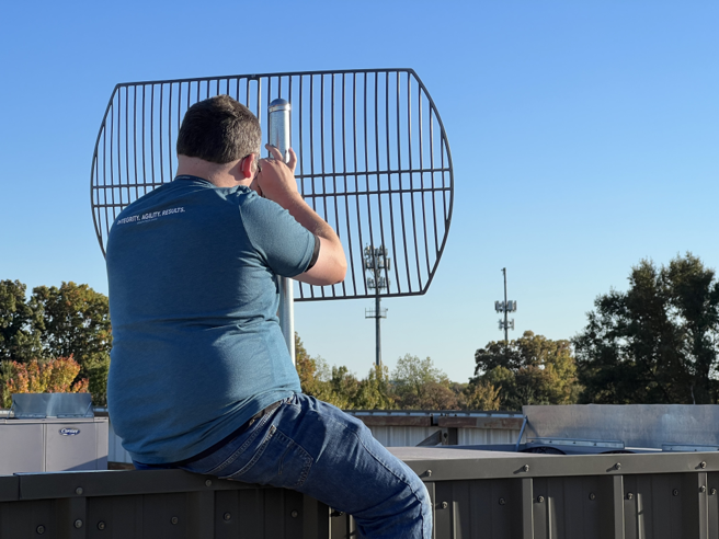
What: Geon purchased a “Griddy” parabolic antenna from the company called Waveform with their headquarters in Irvine, California. This antenna is the first functional component in our diagram above. This parabolic antenna provides 14 to 20 dBi of gain and isolates the towers and cells closest to our roof. The beam angle of our antenna was aligned to capture the two towers seen in the picture below.
Radio Frequency over Fiber (RFoF)
What: RFoF uses converters to transmit radio frequency (RF) spectrum into light that can travel on fiber optic cable. Geon purchased RFoF modules from the company called Optical Zonu which has a headquarters in Los Angeles, California. A transmit (Tx) module is used to receive the signal of interest on the roof and convert RF to light. Then the receive (Rx) module that is within our building converts from light back to RF as seen in the functional block diagram above. A fiber optic cable is used to connect the two modules with little to no loss from the cable itself.
Why: There does exist a roughly 1.5 dB conversion loss from the RFoF transceiver setup, yet after this loss, the system is almost lossless at any distance. RFoF performs better than traditional RF cables, especially at long routing distances, and are used in our setup to optimize signal quality.
Amplifier Saturation and Load Balancing
What: Within our RFoF transmitter exists an integrated low noise amplifier (LNA). The LNA helps boost low signals while adding very little noise to the system. The LNA would be ideal for looking at neighboring towers farther away. However, in our current setup, we are looking at signals with very close transmitters that have high power. A good practice is to measure and make sure to not saturate any amplifier.
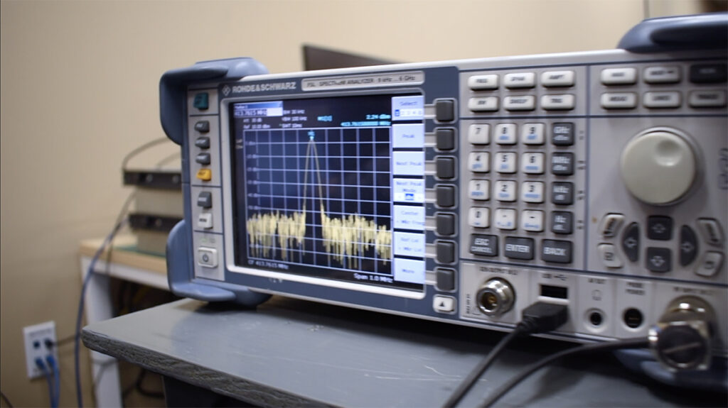
Why: In the picture below, an attenuator is used to lower the incoming signal strength going into the amplifier. Too loud of a signal can lead to oversaturation of the amplifier, which will compress the signal, raising the noise floor around the signal of interest and lowering the signal quality. Too quiet of a signal (or too much attenuation) can cause undersaturation of the amplifier and hurt signal quality. Instead, load balancing to find the optimal attenuation and signal strength can lead to the ideal signal quality.
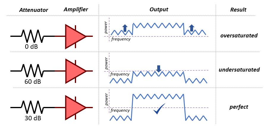
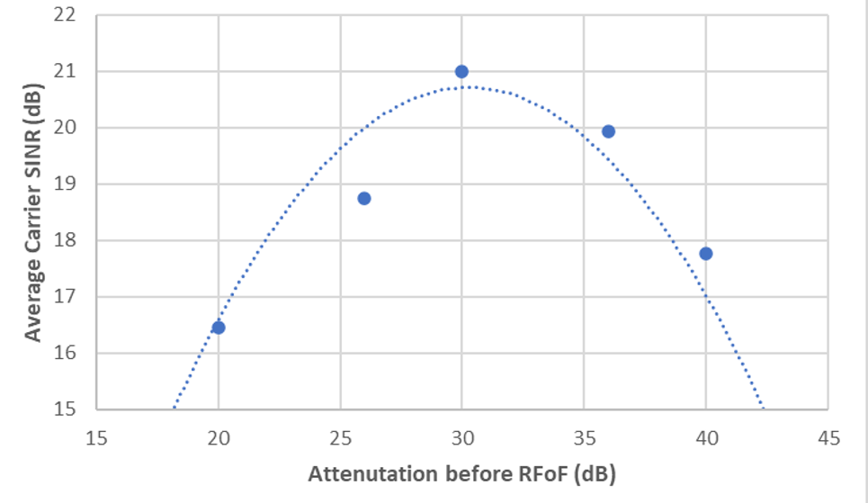
Optimization: To find the optimal attenuation for our RF scenario, we used variable attenuators from the company DigiKey installed before the RFoF and measured the average signal quality over 15x different LTE frequency carriers in the form of signal-to-noise plus interference ratio (SINR). As seen in the picture below, 30 dB of attenuation provided the best average carrier SINR and is seen in our functional block diagram above. RF reception was done with an Ettus B205mini software-defined radio (SDR).
SINR Estimation
What: SINR is one of the four major cellular measurements (besides RSRP, RSSI, and RSRQ). SINR provides an understanding of signal quality in terms of signal, noise, and interference. This provides more information in one metric than any other cellular measurement and is preferred.
Channel Estimation: LTE signals using OFDMA are modulated and demodulated to convert from time domain to frequency domain, respectively. In the frequency domain, a resource grid consists of subcarriers (frequency) and symbols (time) to create the smallest resource unit called a resource element. In the picture below, a resource element is a single square. Known sequences, such as “Reference Signals” are used to measure the quality of the channel. The picture below shows how this reference signal can be averaged with a smoothing window and then interpolated to estimate the channel at other resource elements. Channel estimation is important for equalization, or the correction of channel impairments, which leads to better performance of the technology from preventing bit flips all the way to raw throughput.
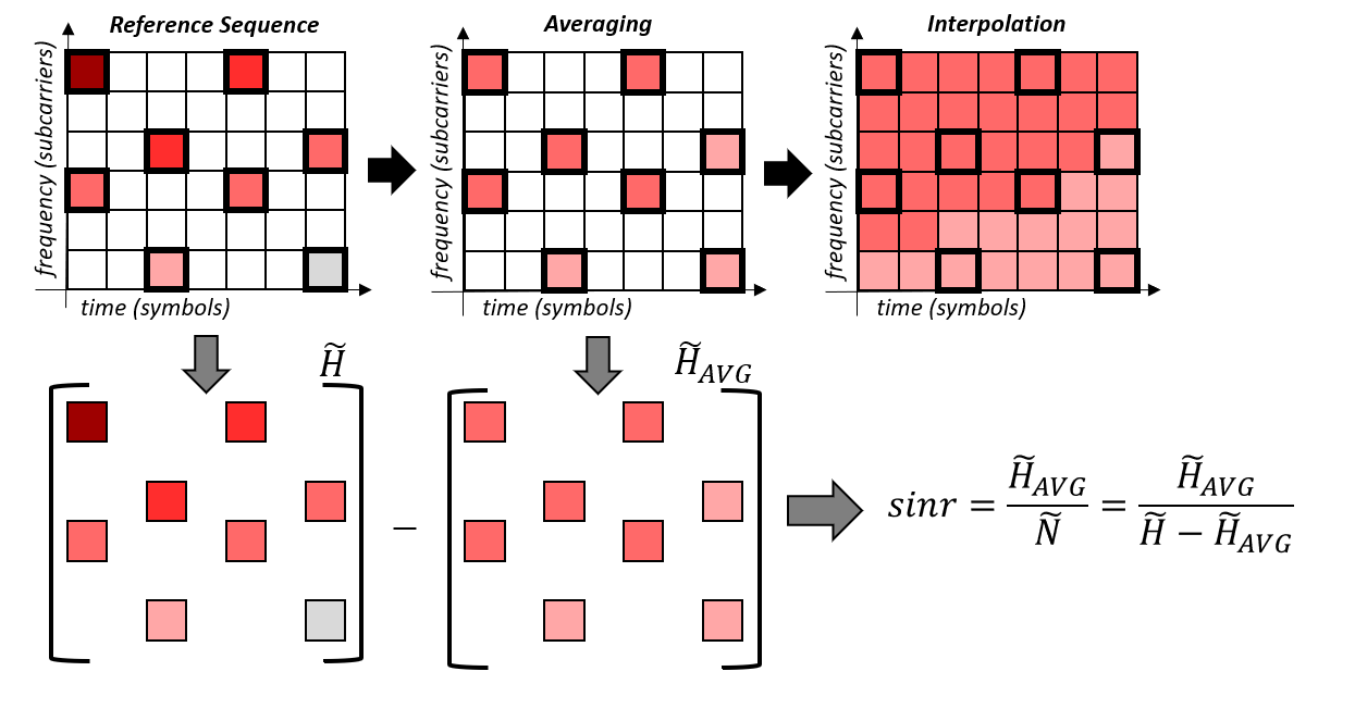
How: SINR can be estimated in many ways as described in [1]. However, one of the most robust methods that also auto-scales to signal strength is the Least Squares (LS) estimate that uses the averaged reference symbols from channel estimation. In the picture above, the original channel estimation and the averaged estimation are subtracted to find a noise estimation. Averaging removes noise, and in this way, subtracting the denoised signal from the original noisy signal provides an estimate of the thermal noise. Then the denoised channel estimate can be used for the signal and interference components of SINR.
- B. W. Stevens and M. F. Younis, “Geospatial Cognitive Networking Protocols and Sensing Algorithms for 5G NR Beamforming,” in IEEE Transactions on Cognitive Communications and Networking, vol. 8, no. 4, pp. 1784-1801, Dec. 2022, doi: 10.1109/TCCN.2022.3204536.
Results
Statistics: In this results section, 15x different LTE frequency carriers at different center frequencies (Fc) are measured to maximize the quality of as many carriers as possible. The SINR for each carrier in each test is determined as well as the average SINR for all carriers and how many carriers are at a “perfect” SINR or above 18 dB. Above 18 dB there are very few bit errors for most common LTE modulations. We desire to maximize both the SINR for as many frequency carriers as possible as well as improve the number of high-quality frequency carriers available.
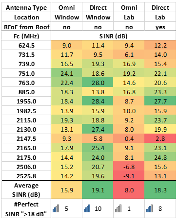
Omni vs Directional: The table above compares the omni and directional antennas taken from the window (with LOS to the towers) of one of Geon’s offices. Going from omni to directional improves the SINR average by 3 dB. Though this may not seem as much gain as expected, using the directional antenna also lowers signals that are coming from other towers which the antenna faces away from. Instead, looking at the increase from 5 to 10 out of 15 perfect carriers gives a better idea of the importance of isolating and improving signal quality.
Omni Window vs Lab: The table above also compares receiving at an office window and within the lab, average SINR goes down by 8 dB and the number of high-quality carriers goes down from 5 to 1. The lab is within Geon’s building (no LOS to the towers) and has attenuation and interference from the structure of the building which creates this loss.
Lab Omni vs RFoF: Within the table above, we can see that the RFoF link performs slightly worse than the directional antenna as the window. This drop in ~1 dB average SINR is because of higher isolation from the directional antenna on the roof which will get less scattering than when it was lower to the ground and because of the small loss in the RFoF conversion. However, the RFoF roof setup still has 8x/15 signals in the perfect or high-quality range. Considering receiving from the lab, the RFoF link provides almost the same quality of signals within the lab as with direct LOS to the tower while being multiple degrees better than an omni antenna within the lab space.
Conclusions:
The setup, optimization process, and results within this post show the importance of using directional antennas and RFoF to support high-quality signal reception from our lab. In the future, we will look at this same setup for 5G NR signals.